Ron's RV7 Aircraft Factory


Welcome to my personal blog. This site was created as an informal description of my build progress in the construction of a Van's RV7 aircraft. A place where family/friends/builders/curiosity seekers can follow along. It is not intended to be a detailed description of every step in the building process as that would be much too time consuming. There are plenty of sites that do a great job in that arena, that is not my intention with this site. My intention is for this to be a philisophical/motivational/inspirational account of the emotional ups and downs of the life changing journey...and it will change your life. I hope this will give you an idea, through my eyes, of what its like to make this transformation. A note to other builders, I am not an expert so do not put your safety at risk by attempting anything you see on this site until you have done your own research, or send me an email so we can discuss it. Any deviations from the plans are not approved, nor endorsed by Van's Aircraft or myself. Thanks for visiting.


Monday, January 23, 2012

Red Tails HOBBS 1082.5 hrs


Saturday night I organized a group outing to go watch the new Lucas film, Red Tails, about the Tuskegee Airmen (TA). I jokingly called it a 'hangar movie night' without the hangar. In attendance were Bryan Raley (RV8 empennage) and his son Adam, Gary and Carolyn Zilik (1600 hr flying RV6A), Sean Thomas (RV7 empennage...recently ordered his wings!) and his girlfriend Diana along with prospective RV8 builder Scott Taylor (who contacted me through VAF...nice meeting you Scott!).

All in all, I think everyone in our group enjoyed the movie and the evening...the theatre was packed, which was surprising and cool to see (second grossing movie of the weekend at 19 million). I enjoyed it  as well but would only call it good--unfortunately, not great. Let me add, its pretty difficult for a pilot that is passionate about aviation, WWII fighter pilots and the P-51D not to like this movie and see it on the big screen.

****spoiler alert---dont read further if you havent yet seen it and want to be surprised******

My only complaints were the storyline didn't evolve much and was a little shallow and predictable (guess who dies in the end?), the villain was cartoonish and the conflict between the hero was left undeveloped, the love story a little unbelievable (I know, I know...who cares about the love story!!??), a couple of the CGI flying scenes showed an air combat maneuver (Cobra maneuver) that is aerodynamically impossible for these planes...but hey, its Hollywood...and the casual movie-goer wouldn't even be aware of this impossibility so I can let that go. There were some historical inconsistency as well, the TA actually flew the P-51C model, rather than the P-51D model which was shown in the movie. I cant complain though...the 'D' model is much sexier! 

On the plus side, at least half the movie was flying scenes...so plenty of flying action, which is never a bad thing for a pilot to consume. Even though a lot of them were CGI, they were very realistic. Cuba Gooding, Jr. is one of my favorite actors and I liked him in this. Even with my minor gripes, I would recommend it. I would just say, sit back and enjoy it and dont overanalyze it like I did! Topping it all off, as usual, the company was great...thanks for coming out guys/gals!

Lastly...I do like the color of choice of the Tuskegee airmen...in case you werent aware, 'Red' is where its at! The color red is associated with lust, passion, love, beauty, and danger.


Wednesday, January 18, 2012

Red Anodize Prep HOBBS 1082.5 hrs

Fellow RV7A builder Bruce Swayze, someone I have actually never met face to face, and is mutual friends with the Zilik's and Mills's, gave me this idea. I am doing a red anodize finish on not only my rudder pedals, but also my canopy side rails, upper canopy support brackets, along with a few other misc parts. Bruce was great, answering all of my questions as I fired them off to him by email several months ago. I've said it before, but again I'll say, it sure is nice to have great people willing to share their time and expertise for other builders. You will find a lot of the "pay it forward" mentality with most builders. This is a great hobby with some fantastic people involved.

The thinking behind this strategy is, I will have a red paint scheme...I've always liked the look of anodizing...it has good wear characteristics...and if I don't like the way it turns out (doubtful) I can always paint over it and I would just be out the cost of the anodizing...not the worst thing. I will post more on this later when I get the parts back from the anodizer...just an update that I took my parts in Monday afternoon. So, hopefully later this week I will get them back...I'm pretty stoked about this, cant wait to see how they come out!


I had my mind made up that red anodizing was the way I wanted to go for the reasons already stated. My only dilemma was...what do I do with the surface to prep it? Usually you will see parts "timesaved", which gives it a nice uniform grained look. Its kinda like using a big belt sander on the surface...purely for cosmetic reasons. Since my parts were already formed (i.e. not flat sheet metal), timesaving probably isn't viable for me. Bruce just left his untouched and he said it looked good, but that any defect in the surface will definitely show. So...I thought, why not "DA" (using a Dual Action orbital sander) the surface...that will give them a uniform appearance and kinda looks cool to me with the swirls...should catch the light for a exotic appearance. So, that's what I did...and it sure looks cool to me...we'll see how it translates to the red anodize finish?


I got the parts prepped and then put a new sanding disc in the sander so it would look uniform for all pieces. After sanding for awhile, the paper loses its bite and has a very subtle, different look which I wanted to avoid...it starts to look more matte. So, keep a fresh piece of sandpaper in your sander...swap out often to keep it consistent.


Remember, you can click on the photos to enlarge them...wadda ya think? Will that dog hunt?? ;) (haha....some 'good ol' boy' humor from my past)


Again, I am a nervous wreck...as I dropped off this box of parts to the Anodizer, I felt like I was dropping off my kids at the baby sitter. Please, please take care of my babies and return them safe and sound and in one piece!! haha! And dont lose any of them! Later this week we'll see the results...cant wait!

Canopy Latch HOBBS 1077.5 hrs

Here we are, after another productive week...I'm starting to make a habit out of this....progress has been excellent lately. ;) With the three day weekend (MLK day) I had an extra day to work on the plane. I've been a ball of energy and enthusiasm lately. I keep saying it, and it bares repeating, I am really enjoying this stage of the build...finally starting to do some actual finishing work, building mechanisms, etc...a lot of excitement for sure.

This week I tackled installing some of the features used for the canopy latching mechanism. As you probably know if you're been reading along, I decided to buy an after market latch from JDAir. I have no regrets on this purchase, good product and good customer service.


These are the brackets that will hold my struts in place. I started fabrication of these but didn't get completely finished. I just need to locate the attach points and I should be good to go...that can wait.


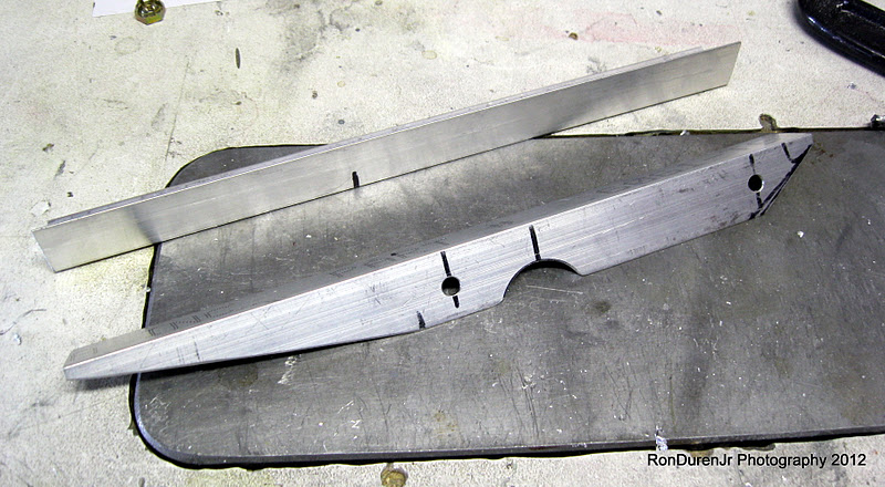
Shifting my focus to the canopy latch. Here you can see the process of fabricating the attach angle brackets that will hold my latch in place. One is done...


For the other, I just did a mirror image and traced the cutout and match drilled the holes. I will note that the 1" diameter hole probably isn't required for both top and bottom brackets (omit the bottom) although I think the plans say to do both. Not a big deal, with side panels it wont be seen on my plane...but it would save you a little work. I will just consider it a weight reduction! :)


I picked up this 1" diameter rotary file at the fly market at OSH last year. It was used and cost me a couple bucks. It was very useful for this little project of adding the 1" cutout and earned its keep already. Handy tool to have in the tool box.


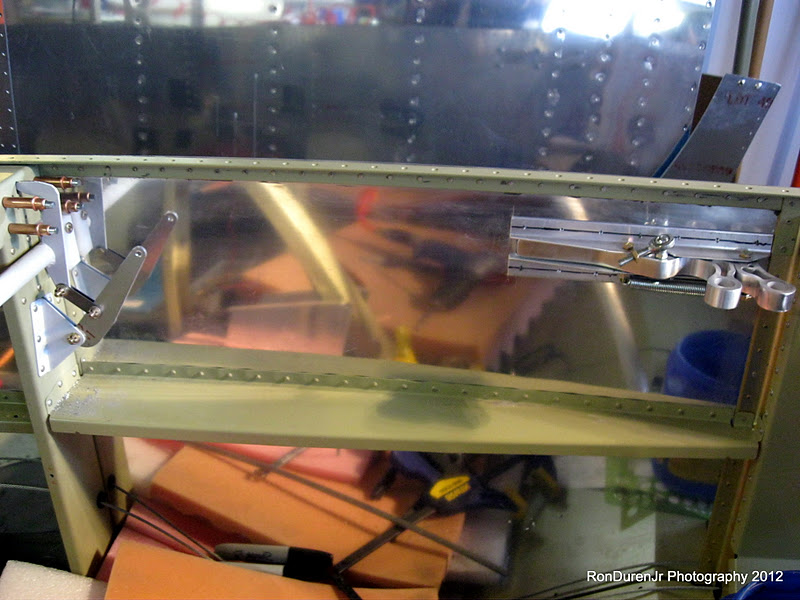
Here you can see the sub-assembly taking shape. This will rivet to the inside of the fuselage. JDAir has .pdf installation drawings on their site for this...and let me add, they are nicely done. My only gripe was that the "full scale" 1:1 template was not actually full scale when I printed it out. Not sure why? Maybe some scaling issues when it was converted to a .pdf. This template is supposed to be used to properly place your cutouts for the latch. It would have been nice to have, but I worked around it...very, very carefully.


Here is the aforementioned cutout layout. I checked everything very carefully...double checked...verified...measured not twice but several times before committing to cutting metal. Yeah, I was a nervous wreck! You just don't "replace" a fuse side skin at this point in the build. It is imperative that there are no mistakes. I could patch a screwup I suppose...but man, I sure didn't want to go down that path.


The cutting into my beautiful fuse skin begins....oh boy! Are we having fun yet! Err on the side of cutting the opening smaller and then open it up gently with a file so you can sneak up on your finish dimensions. Keep doing sanity fit-checks to make sure you are in the right location and have the right size.


Take a jewelers file to smooth out your opening...gratuitious FAA shot.... ;)


Now that the hole is cut, I have my latch sub-assembly clamped in place. Since the template wasn't working for me, my strategy was to cut the holes for the latch first. Position the sub-assembly precisely inside the openings and then match drill the rivet holes for the attach angles. Worked well. Did I mention to be careful....? Work slowly and deliberately....


Coming together...I still had some very subtle filing to do for me to be happy, but this was pretty close to done in this pic. You can also see I have now drilled my rivet holes. All in all, it came out pretty darn good. It doesn't look like it was machined--it does have a hand-crafted look to it, but I'm ok with that. These are the things that make your plane your own...not a machine's. One other note, realize that your reveals (gaps) will need to account for paint thickness so don't make them too tight.


This is the powder coated hooks that will secure the canopy when the latch is actuated. The plans say to "bend" the hooks if necessary to get them to line up with your access holes. I didn't like this strategy...seemed kinda hokey. First of all, they were pretty darn close with no modification. One side was getting hung up though. My strategy was to file the leading edges to remove the sharp points. By doing this, you eliminate catch points. Worked slick. I'll paint that exposed area later.


Putting it all together before cutting the attachment alum rod (seen in pic below) to length and then tapping both ends.


And the finished product...this was cool, being a Mechanical Engineer, I really enjoyed the Engineering involved in the mechanism and the linkages. And the best part is it worked like a charm! This was a satisfying bit of work...and also one that I am glad to have behind me, it was a little nerve wracking as I mentioned.

Tuesday, January 10, 2012

Interior Baggage Compartment Lighting HOBBS 1061.5 hrs

Spent a little bit of time installing LED lights--baggage compartment 'dome' light and a map light that I got from Stein in my last order. Although I am a big fan of LED lights (low cost, low power draw and they last forever) I wasn't overly impressed with the light output of these two guys. It'll be fine for what they need to do.


I'm still fiddling with this and how it will look, but you can see I fabricated a cover for the structural member. This cover isn't included in the kit.


I bought this AC DC switching power supply about a month ago just for stuff like this. This was another great tip from fellow RV7 builder Sean Blair. I hooked this puppy up to my lights and fired 'em up for a test run. Worked great!


Shielded, 3 conductor wire I ordered from Stein for my tail/wing strobes. Does this look like $65 worth of wire?? :) Expensive stuff, but worth it so you don't get EMI in your system.

Monday, January 9, 2012

Aft Fuse Skin HOBBS 1061.5 hrs

This weekend, I tackled getting the aft fuselage skin riveted in place. I made sure I had everything attended to in that area (static ports and routing, wire routing for the tail strobe, etc) of the fuse and figured it wouldn't hinder me to rivet it now. I also wanted to get this riveted so I could do finishing work on my empennage fairing as the cleco's were in the way. So, here are some pics...


Before I get to the aft fuse skin...here are a few shots of my work on the forward canopy structure. After bending the flanges that I showed in a previous post, it was now time to add flanges to the lightening holes....a little more tricky. After considering more creative (ie, complicated) ways to do this, I ended up doing it exactly how Van's suggested....very simple, but effective, as you can see. Just cut a 1/4" notch in a piece of scrap wood and bend them carefully by hand. In this pic, you can see a before and after shot. I liked how this came out. I just took it slow and easy and was very deliberate. Don't try and bend it in one pass...I typically did two to three gradual passes to get the full bend angle I wanted.

When I was doing this task, it dawned on me how much I enjoy stuff like this. Things in the build that you have to do by hand...it takes a steady touch, concentration and some genuine workmanship to get good results. All of which are right up my alley. I also noticed, muck like my Dad, that I had my tongue hanging out while I deep in concentration!! haha! I had to laugh when I noticed this...but hey, Michael Jordan, the greatest basketball player who ever lived, did it too! Anyhow, when I thought about it...whenever my tongue is hanging out, I am very much enjoying myself...lost in the moment. From here on out, it'll be known as the "tongue factor"! ;)


Now that the flanges were done and I got them match drilled and cleco-ed, I shifted to fabricating the little attachment pieces.


Here they are cleco-ed in place...looking good. Some dimpling, edge/hole prep and sanding and these should be done...ready to send to the anodize shop before I rivet them in place.


Ok, now, finally the aft fuse skin. As with most (but not all) of my fuse skins, I am using ProSeal on the overlapping joints. Just for added water and air sealing and also contributing to a better structural joint and less vibration...not really needed, but just a nice touch for my airplane. Mind you, I didn't ProSeal the seams on the bottom of the fuse...I actually want those to leak water if possible. I have recently read about guys putting drain holes in the bottom of the fuse...It certainly makes sense but I need to research this further (I dont think Van's recommends it?) before I commit to drilling holes in my fuse. Drain holes or not...I would rather keep water from entering my fuse if possible, so that's why I did the ProSeal here.


And, after some laborious solo riveting...stretching, grunting, sweating...I got 'em all but these three rivets on each side. The seat belt attachment bracket resides right there and the bolts were getting in the way. I think I will just remove the bolts...rivet it and then rebolt it back in...I'll do that later, this will work for now.


Now that the skin is riveted in place I shifted my attention back to my empennage fairing. I mixed up a batch of 'flox', added some to the inside of the fairing in areas where I needed to close up some of the bigger gaps. This will give me nice a precise fit tailored exactly to the shape of my aircraft...I will do this again with some West systems fairing mixture (micro will also work) for the finishing touches. By the way, I do have clear box tape protecting the skins....hopefully it will peel right off when I remove the fairing for sanding.

Friday, January 6, 2012

Mounting My Tires HOBBS 1050.5 hrs


Like a little kid...I wanted to mount my tires, even though I wasn't really near being ready to put the plane on its gear. I figured this would be a fun little side project.

After some deliberation, I decided to go with a little bit larger tires than the stock 500x5's that Van's suggests. I wanted a little extra tire surface and diameter for the occasional foray into a grass strip (like Johnson Creek in Idaho...its on my aviation bucket list) or even better control on asphalt. I realize the RV's aren't Super Cub's but I have heard the taildraggers do just fine on grass strips...and I plan to use that utility. In addition, I want added diameter which translates to added stopping power. [Edit 01/09/12: After thinking about this statement, its true, but not in this application. The larger diameter must occur at the source of braking. So to get added braking power, I would need to increase the wheel diameter to a 600x6] With my ER tanks, I want all the advantages I can get for a possible aborted takeoff fully loaded. I already upgraded my brake calipers so this fits into my strategy nicely. 

I first thought about putting 600x6's on but my research showed that I would have to modify the axle to do this. I really didn't want to be modifying things if I didn't have to.

Searching the VAF archives, I found several instances of guys putting a metric size tire on with good results, 380x150/15x600. The cool thing about these is they are a direct drop-in replacement. Use the same 5.0 in wheels and tubes, but you get 1.0 or 1.5in (??...these measure 15"...not sure about the 500x5's...some say they are 13.5"...some say 14.0"...I, of course don't have one to measure to verify this) increase in diameter and 1.0in increase in width. And they only add 1.5lbs for the pair (I have not verified this either, just going off another builders notes). So, to me, for my intended mission...this is kind of a no-brainer. It all depends on what your mission is for your plane.


As with almost everything on this project...I had to do some research...to educate myself. I had never mounted aircraft tires before or even seen it done. Figured it couldn't be that tough...right? It wasn't, but the research was helpful. And now I can check this off the list of things I now know about...best thing about building one of these is the education you get along the way. I really enjoy that aspect.

So, first thing I learned...the red dot should line up with the valve stem...


Add talc to the inside of the tire so the tube will easily slide and not bind or pinch. I don't know if they sell something specifically for this, but I figured good ol' baby powder would work just fine as the ingredients say "talc, fragrance". I tried to find a non-scented version...but no joy. Now my airplane smells like a babies bottom! ;) And let me say, it worked just as advertised...the tube easily slid into position when partially inflated.


And there ya go...I threw some air in them, torqued/finalized the bolts (90 in-lbs) and set them off to the side for another day. Although I'm not ready to put it on its gear yet, the time will be here sooner rather than later. That will be a fun day!

Oh, one last thing, I also need to pack the bearings later with Aeroshell 22 grease...they only come with light grease for shipping.

Thursday, January 5, 2012

Forward Canopy HOBBS 1050.5 hrs

So, once I got the finishing kit inventoried and stored...it seemed logical to dig right into it...I can finish my empennage fairing later! ;) I have to admit, my excitement level was pretty high. A lot of builders say that fitting the canopy is the absolute worst part of the project. I'm not sure if I will agree by the end, but for right now, I am pretty jazzed about this part of the build.

Simply put, its the part of the plane where you can really put your signature on your build...a nicely done canopy is the hallmark of good craftmanship in my opinion and I don't expect it to be easy. In addition, this is the enclosure for the occupants so making it look nice is vital since my passengers and myself will be staring at it for many, many flight hours.

I had four days of vacation left after visiting my folks in WA for the holidays and I really wanted to take a big bite out of the project in that time. Mission Accomplished (seen the new version of this movie over the weekend by the way...and really enjoyed it. The building scene where Cruise is jumping around on a rope 130 stories up made my palms sweaty!). I logged 25.5 hrs in four days...easily my best four day solo stretch yet, and the most since my Dad came out to help my with the wings. I have to admit, it was a little exhausting though...working on it everyday. I was ready for a break yesterday.


Getting started on the forward panel area, I started by riveting my seal flanges in place. A rubber seal will attach to these...this area is the #1 area for water leakage into the cockpit. I am already thinking of ways to improve this.


A little unrelated, but I ordered some longer AN3 bolts for my rudder pedal mounts and had them shipped with the finishing kit. Since I am doing a 3/4" raised false floor...it just didn't feel right when I was playing around in the cockpit with my feet on the pedals so I am going to raise the rudder pedals 3/4" to accommodate for this. I'll do this later...I need to make some spacers first.


Just getting started with fitting my forward canopy skin. Looking cool eh? At this point in the instructions it talks about installing this approx. 100 times before you are done!! ouch! A guy takes notice of  a comment like that... :) On the bright side, I already have about 5 of those 100 completed over the weekend!


Release pins for the jettison mechanism. You have to cut the threads off these boys and taper the ends...be careful not to cut them a smidge too short, its easy to do...ask me how I know? Err on the long side...


My jettison mechanism taking shape...I was pretty proud of this until I did a fit check.


Read this detail drawing carefully...the length dimensions for C-621 and C-622 are to the hole centers...NOT the length of the rod. I cut mine wrong so each one is 1/2" too short! dangit! Not paying attention...I should know better, since these are the critical dimensions, it is dimensioned properly...I just missed it. I have some more on order...luckily they're cheap.


As you get ready to match drill through the skin into the round rod in the weldment, I recommend you clamp the support bracket like I did here...they don't say to do it, but it makes good sense.


Here you can see I am getting everything ready so I can drill the hinge brackets. It says to do a 0.020-0.032" reveal between the skins...of course I chose a nice tight 0.020". Looked real nice in this pic...but after I drilled the brackets, to my aggravation, it opened up!! The fun begins...proper fitting is going to be tough I can see. I'll worry about this later, might be a way to hide the larger gap? I have some ideas. Not sure I have any advice as I don't really know why it happened or if this is common?


In this photo you can see I have riveted the splice plate in place. I threw in four extra rivets on the return flange for extra strength. I couldn't understand why Van's didn't do this?? Well, now I know...later you will add some support pieces in that location (see pics in this post at the end). So, don't try to be clever like I did...its not a big deal but kind of a pain.


I used my strap here to get a nice tight fit with the forward canopy assembly before drilling the hinges. Van's says to use duct tape...I thought this worked much better and would recommend it.


Press in brass bushings...Van's recommend a reamer for these holes, which would've been nice. I didn't have one and wasn't going to buy one for just this, so I just just used a regular drill bit. Consequently, they weren't a press fit...I used some RTV to keep them in place.


This was the first shot of my canopy open after drilling the hinge brackets...cool.


Support brackets on the forward canopy. These are new for the RV7's from what I can tell...the 6's didn't have them. I really like this addition...they add some real stiffness to the frame, look cool, and were pretty fun to fabricate. You have to bend these flanges first...more on these later, as I am only part of the way done with them in this pic.