Ron's RV7 Aircraft Factory


Welcome to my personal blog. This site was created as an informal description of my build progress in the construction of a Van's RV7 aircraft. A place where family/friends/builders/curiosity seekers can follow along. It is not intended to be a detailed description of every step in the building process as that would be much too time consuming. There are plenty of sites that do a great job in that arena, that is not my intention with this site. My intention is for this to be a philisophical/motivational/inspirational account of the emotional ups and downs of the life changing journey...and it will change your life. I hope this will give you an idea, through my eyes, of what its like to make this transformation. A note to other builders, I am not an expert so do not put your safety at risk by attempting anything you see on this site until you have done your own research, or send me an email so we can discuss it. Any deviations from the plans are not approved, nor endorsed by Van's Aircraft or myself. Thanks for visiting.


Wednesday, November 25, 2009

New Dynon Skyview HOBBS 160.0 hrs

As you may have noticed, the project has been slowing down for me. My strategy is to pay for the entire airframe with cash, which will serve as my down payment, to finance the completion of the project. So...there will be a small lull in activity while I save money for the wings.

I have been working on the tips here and there. They're looking nice, I think I am going to like the finished results. I'll post more on this later as I near completion.

So, when not building, the next best thing is dreaming/planning paint schemes, cockpit designs and avionics. Which, I gotta say, is quite fun! The avionics out there on the market for kit built planes is utterly amazing these days. I plan to have a 'glass' cockpit in my plane. For several reasons: #1, I have flown a G1000 and am amazed at the added safety these systems CAN add to your flying. You still need to practice good situational awarenesss and see and avoid techniques, but adding the features a glass panel provides is key for safe flying. #2, glass cockpits are definitely the future of aviation. And #3, I am a 'tech geek' and these glass panels are really cool!

I am considering several MFD (Multi Function Display) and PFD (Primary Flight Display) options. I think I have narrowed it down to two companies.

The first is Advanced Flight Systems. I really like their new Advanced DECK.

Advanced Flight Systems

Second is the new Dynon Skyview. This just came out this year at Sun-n-Fun. Dynon has been around in the kitplane market for quite some time and most of the guys have had nothing but good things to say about them. Namely, they seem to have great value for the money, homebuilders love that! :) I personally didnt like the look of their previous flight displays...frankly, they look kind of cheap. But this one changes that, the look of this new one is much more professional in its styling. It appears that Dynon is growing up and ready to play with the big boys in the market. That, along with their good track record in the homebuilt market, has me interested.


Both of these have the capability of using SV (Synthetic Vision), which is on my wish list. This is when you can see the 'virtual' landscape of the geography you are flying over right on your flight display, no matter the visibilty outside. Another great safety feature to have and also the way of the future. You can see it in action on the Dynon video.

Happy Turkey Day 2009!!! ...KPR (Keep Pounding Rivets!)

Sunday, November 15, 2009

Tips Continued.... HOBBS 154.0 hrs

And now the time consuming part starts. In the previous post I showed how I had fit and trimmed the tips and got them ready for install. One thing that I forgot to get a picture of is the aluminum strips I glued to the inside of the tips. The aluminum strips act to add strength for the pop rivets that are installed and dont pull through. Here you can see the first step. The holes have been match drilled. The tips have been countersunk and the aluminum has been dimpled in preperation for the pop rivets.


In my last post I mentioned the blue foam that I used to close the HS tip. Well, here you can see where that blue foam resides. Underneath the special fairing epoxy (the rust color, basically this is aircraft 'bondo') is the blue foam that has been glassed in place.


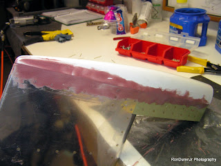
You can see the fairing work I am doing here on the elevators. Basically I am filling the seam, the pop rivet heads and low spots.


After it dries, I sand it to remove some of the excess fairing material and smooth the contours. I am getting it ready to glass the seam.


In this view, you can see how the two tips are starting to take shape. I will do several iterative processes to get these to match up nicely before I am done.


Its a little hard to see, but in this view I have added a 1" fiberglass strip over the seam. This is insurance to prevent the seam from cracking under the paint later. I use 'peel ply' over the fiberglass to keep it as smooth as possible.


This view shows the fiberglass tape after it has dried and the peel ply has been removed.


By adding the fiberglass strip, it adds a little height to the seam. So now I am using my fairing to not only fill the weave of the fiberglass but also to blend it into the sheet metal. I used a nice straight edge to get a real nice flat transition and to also fill any low spots I may have missed in the previous step. I am getting real close to being done with this. Now I will sand it smooth.


I wanted to show this shot because I really made the 'micro' very dry in this batch. By making it so dry, it was very thick in consistency...thick peanut butter-like. At first I thought it was too thick, but it really worked well for what I was trying to do. This was kind of a breakthrough in my education, in the future I will try to repeat this consistency.

Empennage Fiberglass Tips HOBBS 150.0 hrs

Now that the metal work is done, it is time to fit and blend the fiberglass tips onto the sheet metal. Vans recommends using blind rivets to attach the tips and call it good. Leaving the seams and rivets visible. You have to remember, Vans is very utilitarian in their aircraft design philosophy. Cheap, light and very basic is their building motto. Now, for me, that's quite boring. Half the fun of doing one of these planes is putting your personal touches on it, doing something to seperate it from the 'garden variety' RV7. Building it in a way that shows some craftmanship. So, with all that being said, I am doing this task a little different. I will fair the seams and fiberglass and rivet the tips in place. When I'm done, you will not see any seams, the tips will blend perfectly into the sheet metal so you wont know where one begins and the other ends. Not an original idea, plenty (most) builders do it this way. It looks very nice when done right. This is a time consuming task to do it this way, it also will add a little weight and expense.


So here is the HS with the elevators attached for fitting.


Here is the first fitting, I have just set the tips (white parts) in place so that I can get an idea where I need to trim the fiberglass for a good fit.


Here you can see the marks for trimming. I will use the dremel tool to trim away some of the fiberglass so that it fits nicely over the counterweight.


After trmming this is what it looks like.


And in this photo, if you look close you can see where it was trimmed. Underneath the tip is the lead counterweight.


Another shot of the tips in place, slowly trimming them down to a size I am happy with. If you look close,  you can see the blue foam that I used to close off the HS tip. I fiberglassed the foam in place to close off this gap.


You can start to see how the tips really make it look aerodynamic and clean. The tips give it a nice finished look. When I am finshed I will spray the tips with a filler/primer and they will look very nice if all goes well.

Drilling the Control Arms HOBBS 146.0 hrs

This is a task in the project where you need to 'match' drill the two control arms. Its a little tricky because the final size of the hole is 0.25" diameter and match it to the center bearing. So what I did was place a bushing with an outside diameter of 0.25" and inside diameter of 0.125". I placed the bushing inside the bearing and drilled a 0.125" pilot hole in both control arms. Then I disassembled the elevators and final drilled the holes to 0.25". This process gives me holes in both control arms that are aligned with each other and also with the bearing. Worked pretty slick.