Ron's RV7 Aircraft Factory


Welcome to my personal blog. This site was created as an informal description of my build progress in the construction of a Van's RV7 aircraft. A place where family/friends/builders/curiosity seekers can follow along. It is not intended to be a detailed description of every step in the building process as that would be much too time consuming. There are plenty of sites that do a great job in that arena, that is not my intention with this site. My intention is for this to be a philisophical/motivational/inspirational account of the emotional ups and downs of the life changing journey...and it will change your life. I hope this will give you an idea, through my eyes, of what its like to make this transformation. A note to other builders, I am not an expert so do not put your safety at risk by attempting anything you see on this site until you have done your own research, or send me an email so we can discuss it. Any deviations from the plans are not approved, nor endorsed by Van's Aircraft or myself. Thanks for visiting.


Thursday, March 21, 2013

Navy Tiger Cruise!! HOBBS 1827.0 hrs

 
I just found out yesterday that I am getting the once-in-a-lifetime opportunity to go on a Navy Tiger Cruise aboard the USS JOHN C. STENNIS (CVN 74). Its an active duty nuclear powered aircraft carrier. We will be sailing out of Honolulu, docking in San Diego five days later.
 
If you are unaware, like I was, a Tiger Cruise is essentially a sort of appreciation cruise for family/friends of active duty personnel. No, I don't have any kids in the Navy...that I know of...this opportunity presented itself through some of my RV friends. I really was extremely fortunate to even be in the conversation to be honest, it was happenstance.
 
During the cruise, we will be treated to an airshow at sea, which will be worth the price of admission alone! Watching flight ops will be unbelievable.
 
There are five of us in our group and I am the only one without a flying RV. The plan is to fly their RV's from Denver to San Diego, overnight in SAN and then hop a one way commercial flight into Honolulu a couple days before departing on the Stennis. After returning to San Diego aboard the Stennis, we will then fly the RV's back to Denver. What a trip eh??
 
How this affects the Factory...? Well, I had to reschedule my transition training with Alex (he was great about doing this for me) to May 4th. Of course, this will delay everything on the project by about ten days as I will be on vacation about that long. But...its a no-brainer to take advantage of this, the plane can wait, it'll be here when I get back.


Doubtful we will see anything like this, but what a cool shot eh?

 
A parting shot of the Stennis in Honolulu...sailing past the Arizona monument in a moment of silence will be surreal. I can't wait, this should be amazing! A helluva birthday present for me that's for sure.

Slowly but Surely HOBBS 1827.0 hrs

I didn't log as many hours in the Factory this week. A couple things contributed to this. One, we had a record breaking 76 degree day on Friday, so I met some friends for a patio happy hour (hey, a guy has to have some fun sometime!). And two, I was feeling a little bit overworked and underpaid...so I took Sunday off completely. Which I realized was the first Sunday I haven't worked on the plane in months. Bottom line, I needed a breather, and it was a nice break.
 
But as I always say, breaks are fine...but keep them short and get back at it if you want to finish in a reasonable time frame. Nothing wrong with slow and steady. So...I am still progressing, slowly but surely advancing on "first flight" day.


Sure enough, I realized I didn't order enough shielded cable on my last order...I forgot about the headphone jacks needing it also. I buy my shielded cable from SteinAir. While I was on the site poking around to see if there was anything else I needed, I came across this new product Stein is offering....wheel chocks. Sure, easy to make yourself, but what I liked was the engraved N-number...and I gotta be honest, it saved me an hour or two of work to drill all those lightening holes and otherwise fabricate my own. The best part, they were only $29 for not one set...but a pair! You couldn't buy the material for a whole lot less than that and certainly couldn't have a machine shop engrave your N-number for anywhere near that cost.
 
There are very few things on this build that I spend my money and say...that was well worth it. Almost everything in this hobby is highway robbery. My Crow harnesses come to mind as being a GREAT value...and definitely these wheel chocks fit the mold, I recommend them.

 
Soldering, shrink tubing, labeling my headphone jacks...do everything you can to keep these wires secure and free from vibration. How many times have you heard of headphone jacks that are intermittent? Usually just wiggle it and it'll work again. Most likely due a loose solder joint is my guess...remember, solder joints don't like vibration.

 
Wire routing of the headphone jacks...I usually don't like the adhesive stick on tie-wrap holders, but you can see I am giving them a try...we'll see how the adhesive holds up over time, in my past they tended to get brittle and break off.

 
A TNC (threaded NeillConcelman) connector for the Dynon transponder. They don't send you one (grrr), so you'll have to source your own. Luckily there is a local electronics store here in Boulder that carried these so I saved shipping costs. The TNC is the same as the BNC (Bayonet style) which is the more common version, this one is just threaded.


If you are using the PSEngineering PAR100EX, make sure you read the manual BEFORE powering this baby up! It comes configured for a 24 volt system, to switch it over to a 12 volt system you will need to remove the cover and move the red jumpers as indicated in the manual. Don't forget or you'll have a paperweight.

 
Trying to figure out my last few fuel lines in the FWF before putting one last order in to Bonaco. One of which is the fuel line running from the fuel injection servo to the fuel distribution "spider" on top of the engine. I suppose there are many different paths you could take to get this done. I want to keep all fuel lines as short as possible to reduce vapor lock potential with hot fuel so I chose the most direct route. This happens to be straight up through the bottom baffle. 
 
Removing and then reinstalling this puppy was a little tedious, but its doable. As you can see, I drilled and inserted a rubber grommet for the fuel line routing.


And bam...there is where it enters the spider...came out well.

 
The other end attaches to the servo...I am still playing around with this fuel line routing to keep it away from the crossover exhaust as much as possible...what you see here is not final.

Monday, March 18, 2013

Registering Your Homebuilt HOBBS 1814.5 hrs


I want to offer a few quick tips and my insight into starting the paperwork dance with the FAA. First and foremost, I started with this very helpful checklist published by the EAA homebuilders site. Reading through this, you will see multiple helpful links to documents you will need. Nice work EAA!

Specifically, lets jump right to the "registration" section. Two things to keep in mind, having an N-number reserved doesn't mean your homebuilt is registered with the FAA. Secondly, until your kit is registered, you cant get your airworthiness certification from the DAR/FSDO, they wont even show up until you have this completed.

You'll notice the list says to start this process 90 days in advance, while the FAA Advisory Circular (AC) 20-27G states 60-120 days in advance. I thought 60 days should suffice, consequently I mailed mine on March 13th. I just got off the phone with the FAA representative today and she said she would be mailing this back to me next week. I'm a little confused why the large difference in timeframe??...but I'll be thrilled if this actually happens, I may have dodged a bullet since I thought I was going to be waiting on paperwork to fly. The bottom line is, my advice is get this done as soon as possible. There really is no penalty to doing it early as long as their isn't tax implications to contend with in your state.

These are the steps you need to take to get this process started:
  1. Send an email to Cynthia (as of 5/18/13) at Van's (cynthias@vansaircraft.com) requesting 'bill of sale' information from Van's, and specifically your 8050-2. She will email you some forms to fill out and get notarized (check with your bank or credit union...they usually do this free of charge for customers), which you will scan and email back to her. She then mails an original signed copy of your 8050-2 to you. They need this by Thursday each week to mail out on Friday. Expect all of this to take 5-7 days total.
  2. Go to your local FSDO to obtain a 8050-1 form. You can't get this form via the internet and must physically get it from them since it is in duplicate form. Fill it out and detach the pink copy for yourself.
  3. Fill out form 8050-88 (available on the internet) and get it notarized.
  4. Mail this entire packet (all three forms...originals, not copies) to the FAA in Oklahoma, make sure everything is correct and signed...standard 'error checking' to prevent delays.
This isn't all of it by any means, but these are the first steps...I'll post more as I work my way through the process.

Edit 05/15/13: Check out the follow up post for some "gotcha's"

Thursday, March 14, 2013

Headset Jack Location HOBBS 1814.5 hrs

 
See ya later 1800 hr threshold...bring on 1900! As you can see, still cranking along at a good clip. Although there are days I am feeling the fatigue, it has been a lot of fun lately in the Factory. I'm expecting my final total to be around 1950-2000 hrs...we'll see how that plays out. Bottom line, it'll be done when it's done.
 
On the last two Saturdays, we have been hit with two spring blizzards. Both times, I drove my 4x4 truck to the hangar through blinding snow--cant let a little blizzard stop you when you are building an airplane. Of course, the hangar row was like a ghost town...no one to be seen but little old me.


One of the cool things about my new hangar location, other than the fact it is a very nice hangar with great hangar mates...is its geographic location. I learned to fly at this airport (KBJC) and the views of the Boulder Flatirons (remember you can click on the photo for a larger view) are nothing short of spectacular! My favorite views of the Flatirons are when there is a fresh coat of snow on them coupled with a bright sunny day, which we get a lot of. Views like this are just one of the many joys of living in the great state of Colorado!
 
 
Ok, back to airplane stuff...more work on the sticks. These are fun...I am learning that I really enjoy anything and everything related to pilot/co-pilot interfaces. Items that I know I'll be seeing/using on a regular basis inside the cockpit. This is the co-pilot stick. The tubing is slightly smaller than the pilot side since it can be removed and it nests inside the larger mount housing.
 
This makes the tubing too small in diameter to properly fit the grips. You have to come up with some way to add a "spacer" to accommodate this. I just used a section of the pilot stick that I cut off (you will need to cut these to your desired length). I then slipped that over the co-pilot stick and you're almost there. There was just a little slop in the assembly as the two tubes didn't fit tight. I suppose you could just leave that little bit of 'slop' and be fine from a safety standpoint. But I didn't want a sloppy feeling stick...I wanted it to feel solid. But how to close up that very small space between the two??
 
I just mixed up a batch of epoxy flox...coated the spacer gap, used a drift pin to keep everything aligned and let it set up overnight. Worked perfectly. In these two pics you can see how it all goes together. Of course, I will do a little touch up on the paint later to make it look pretty again.


As I started getting into wiring or at least thinking about wiring my sticks, it dawned on me that it would be a major pain to do all this while the stick assembly is in place in the cockpit. I found some posts on VAF of a modification where builders cut two more of the seat pan ribs so the entire assembly could be removed and assembled on the bench. After some deliberation, I decided to go this route also (btw...Van's approves this mod)...it seemed like a no-brainer to do this for easier access.
 
Notice the red sharpie marks in the pic...that's where I will cut the ribs and fabricate removable spacers just like the inner two ribs have. The ribs are actually pre-punched for this...notice the holes.


Here is what it looks like after some cutting...you should get the idea now. More work on the sticks will come later. I am debating exactly how I want to wire my co-pilot stick to make it easy to remove...there are a couple options I am contemplating.
 
 
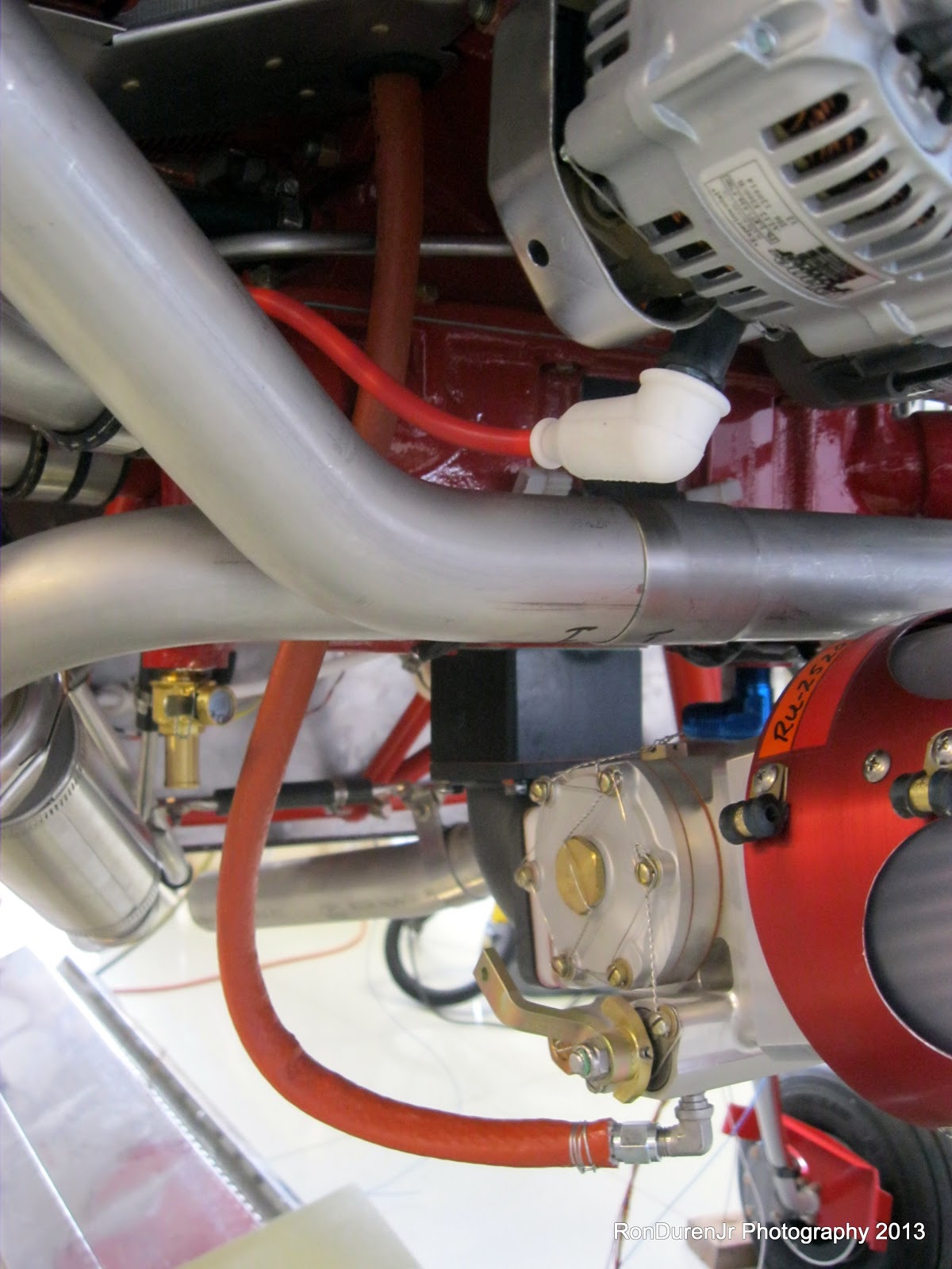
I am trying to get all of my antenna's wired right now...its pretty amazing how many of them there are on this little airplane! 2 comms...transponder...UAT (ADS-B)...Garmin/XM GPS....Skyview GPS...6 total and this isn't even an IFR bird!
 
So this pic shows the Garmin SL40 Comm coax connector assembly. As you can see, it is a right angle version with a blind mate connection so that it automatically docks when you insert your comm unit.

 
This was my first experience with a coax right angle connector. Luckily, the installation manual had great documentation on how to tackle this. Its pretty similar to a straight coax connector, except you have to solder the conductor inside the housing. Not too tough...pretty intuitive actually.

 
And the finished product...this will now be screwed (and allowed to "float") to the back of the mounting trayfor the SL40.

 
Moving on...yes, bouncing around like I always do. Wired in the flap motor. Did a full range of motion test to ensure the wires had enough slack to move with the assembly...good to go. Also notice my service loop, which is always a good idea for future maintenance.

 
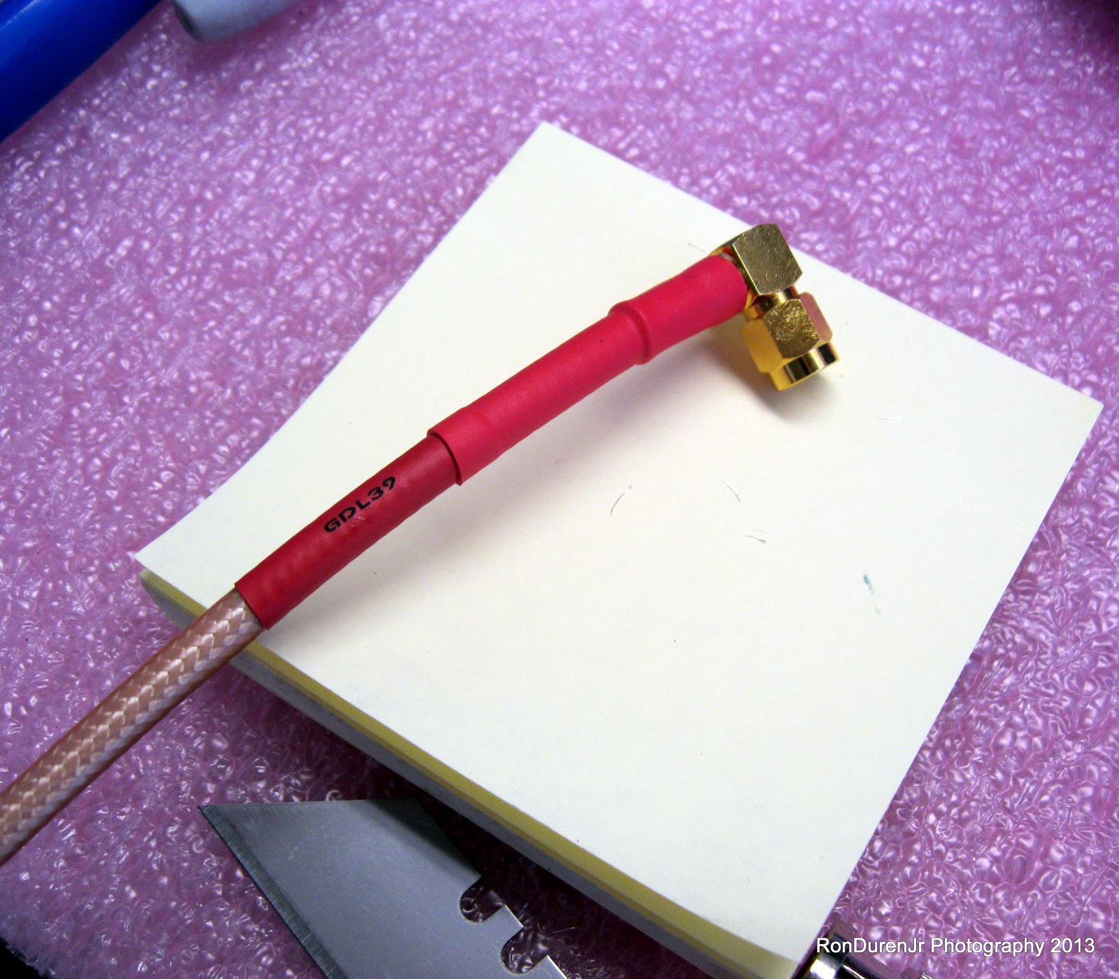
More antenna wiring...this is the connector that goes to the GDL39 for ADS-B...it then connects to my UAT blade antenna on the belly of the plane. I had to buy this right angle SMA connector from a local electronics store (JB Saunders) since Garmin doesn't supply you with one...surprise, surprise. You will need to do the same soldering excercise with this baby. You can either go right angle like I did or buy an adapter (Stein carries these). I wanted this setup because each connector in the system introduces some Db loss so keep them to a minimum if possible.

 
Moving to the baggage area. I thought long and hard about where to put my headset jacks. These were some of my selection criteria:
  1. Away from the controls and throttle, so this eliminated the center console as a choice.
  2. Able to plug/unplug while strapped in my harness...I didn't want to have to unbuckle my shoulder harness to plug them in or out.
  3. Not obstructing the area between the cockpit and the baggage area, i.e., can my co-pilot reach into the back without moving the cords?
  4. Fairly easy to reach for in-flight trouble shooting...again without unbuckling.
  5. Out of the cockpit area if possible to keep cord clutter to a minimum.
Many of my cockpit influences (center console, throttle location, map light) are from the Diamond cockpit since it is a cockpit layout I mostly like and is one I have experience with. The DA20 has the jacks right behind the seats essentially on the cross support. This is nice to keep the jacks out of the cockpit area...but unless you are a contortionist, you cant reach back to plug those puppies in while strapped in. So, that idea was out for me.
 
But, leveraging the idea of getting them out of the cockpit area. I chose to mount them on the upper support facing to the side. The difference from the DA20 is these are mounted high so I can reach them. With this setup I was able to address all five of my criteria, which is always good in product design. I will also add a couple cord clips on the rear of the roll bar to keep them from hanging down...the cord routing will come over my outside shoulder. 
 
Before deciding on this location, I actually installed my seats and put on my headset to get a feel for the layout. I can reach the jacks without unstrapping. I was thrilled with this location choice. Although I will tell you...I cant wait until the day we have "cordless" headsets...with technology nowadays that cant be far off. A blue tooth headset maybe?? 

 
This support piece where the jacks are installed is supposed to be left open according to the plans. I really despised that unfinished look so I fabricated a cover plate that will also hold a baggage dome light, a map light and a clothes/coat hangar. Here is how I did my clothes/coat hangar. Just riveted a doubler in for strength and bought a simple black anodized drawer handle.


The wiring inside the cover...notice the shrink tubing is not 'finalized' yet until I know I have a functioning system...think troublshooting.

 
And the finished product assembled for a test fit...and yes I tested the lights also. I really liked how this came out. The map light is copied directly from where the map light is located in the DA20.

Friday, March 8, 2013

Mid Fuse HOBBS 1793.5 hrs

First off, let me apologize, I just realized I didn't take many pics this week. You know you are preoccupied when you not only forget to take pics, but also not even realize that you didn't take many pics until you look at the camera! :) Its a great indication how focused I am right now on getting things done. As evidenced by another strong week in the Factory, logging 22 hrs, closing in on 1800 hrs on the HOBBS....wow!
 
In other news, I contacted a local DAR, visited the Denver FSDO and started the registration application process with the FAA...much more on this later. For now I'll just say...I should've started this much sooner, I may have screwed myself a little bit in the fact I will have a flyable airplane and be waiting on paperwork to get it in the air...ugh.
 
 
As you know, the plan is to work my way from the tail forward. The tail is 95% ready to go...just dragging my feet on doing that last fiberglass work on the cap...in due time though. Next up, is moving through the fuse toward the cockpit. Mainly this is the mid-fuse that I am now focusing on.
 
Behind my baggage bulkhead resides my ELT (wired and finalized the antenna) and Dynon A/P pitch servo. I also planned to mount my PAR100EX (second comm) remote radio module and the remote Dynon transponder back there. The reason being, the tip up canopies are notorious for leaking water...I figured why not mount as much expensive electronics in other places as possible. Also, if my main Garmin SL40 gets wet...having a second one in a dry environment offers good backup redundancy.
 
First order of business was how/where to mount them? Well, another one of those tasks that you spend a couple hours thinking about it and a half hour actually doing it. I decided to build a small tray to hold both components. You can see three large holes I added as lightening holes. 
 
Disclaimer: I don't know if I will get any EMI interference mounting these so close to the A/P servo? Both manuals for the components didn't mention any kind of warning that I could see. But...I decided, just build it, test it later...EMI interference is very hard to predict...and I can move them later if I need to.

 
The Dynon transponder has a nice clip in tray for easy removal. You can see, my lightening hole didn't come out concentric...oops. Oh well, you'll never see it...and it adds character. ;)

 
Both components mounted on the tray. The tray was then pop riveted (and sealed with my paintable silicone) directly to the bottom of the fuse. You can see my transponder antenna from Delta Pop in the background. I mounted this almost directly below the transponder. I will post some pics of the entire setup later.

 
Lastly, I started to wire in my infinity stick grips and also cut the sticks to length...this is the co-pilot side. Here is what the grip looks like when disassembled. I will post more on these installation details later...but it is in progress as I write this, and its kinda fun.

Friday, March 1, 2013

Appendages HOBBS 1771.5 hrs

As you know, I set out to get the tailfeathers finalized and ready for flight once I got moved into the hangar. This effort is going well, although eating up a lot more time than I anticipated, but I'm almost there. Right now it is mostly just rudder stuff left to do. While I dink around with rudder cap fiberglass work, I am staying busy working on getting the other appendages--the wings, also ready for flight. This includes riveting the last bottom skins in place, plumbing the aux fuel tanks and finishing up misc wiring tasks.

This was one of my best weeks in regards to hours worked...I logged 23.5 hrs out at the hangar, I am like a shark that senses blood in the water right now! Full of enthusiasm, full steam ahead!


Here are a few shots of my rudder cap with wiring conduit and a support piece bonded in place. Remember, I am closing up the rudder cap permanently so this should suffice. Notice that I didnt bond the side of the support piece, when it is riveted to the rudder it needs to be able to flex inward.

 
With all of my wiring tasks, I am using my power supply to test each component before install. Here is the tail strobe in action. As much as I am uncomfortable with wiring...it sure is fun when you wire something together, apply power,...and it actually WORKS!!
 
 
If you've never wired in a D-Sub connector (this is a DB-9...9 pins for this version), this is what the finished goods should look like inside the housing...don't forget your 'strain relief' bracket.

 
I dab some removable loctite on the attachment nuts shown here. I worry about these things coming loose.


Moving to the wings...after much debate, I decided to ground my taxi/landing HID Duckworks lights locally instead of running a ground wire all the way back to the firewall "forest of tabs". Nothing wrong with that approach, I just don't feel its needed. I used a one conductor shielded wire for these. I used a wire brush attachment in my dremel tool to remove the paint...don't forget this for a good ground path.

 
This is how my final configuration looks...notice there are two ground wires attached to the ground screw...one is the shield (ground only one end) and the other is the ground coming off the light itself.

 
And once again...test time...looking good...next task!

 
Left wing...last bottom skin...done, riveted in place...solo! Sweet!


Right wing...last bottom skin...done! We're getting there.

 
I bought this aluminum AN hardware last summer at OSH...hard to find and works great for mounting your ADAHARS, which requires non-magnetic hardware.

 
The lock on the right is my original choice for my baggage compartment storage areas. The paddle latch from Southco on the left is what fellow RV7 builder Brian Beatty suggested...I am swapping them out. I have no idea why I thought I needed to lock these areas?? I will use one compartment for spare oil and tools, the other will have a first aid kit and a couple survival items. More details on this later.

 
Time for some homework...if you are building one of these, you will know, its not all building time that goes into the final product. There are countless hours of research and education that go on in your "free" time. These two AC's are on the topics of registering your homebuilt and flight testing. I encourage you to read up on this stuff.