I suppose one other thing may have had something to do with my burst of enthusiasm is I have now targeted being done and flying in a year and a half...so my birthday month of April, 2013. There it is in black and white for the world to see! haha! And I've had more than one person say they dont think I will be able to pull it off...hmm, maybe they're right, but it sounds like a challenge to me. ;)
I do believe its a realistic goal, if not a challenge...I plan to average 15 hrs a week and if I can do that, I will be right around 1985 hrs by April. Since Van's estimates 1600 hrs to build one of these in a generic sense, with my custom mods, I am guessing right around 2000 hrs for my airplane. Not sure if I can pull this off, but I plan to give it a helluva try! So...follow along, as I try and get this puppy flying by April 2013!!

Here's my procedure. I first match drilled through the skins with the gussets removed. I then installed the gussets by bolting them in place to the spar carry through. I just used the 1/4" bolts for this task and skipped the big 7/16" bolts--but you need to snug it up tight for a proper fit before match drilling. Once I had it snug, I marked the hole (green dot) closest to the spar carry through. I then removed it...measured to the center of my hole marking and extended a centerline on that dimension (red line).
Here is is in place...the bolts are just loosely inserted for now. I think I will need to have remove them to get the 1/4" bolts into the wing spar so for now I will just leave them like this.
I ordered some 3/4" soundproofing foam from ACS. This is aircraft grade foam with FAA approved fire ratings. It also does not absorb moisture. Take the fire rating for what its worth...its better than non-FAA approved foam, but although I didn't test it, my guess is it will burn if exposed to the right environment. So, if you do this mod, weigh this information accordingly and do your own personal risk assessment. Right now I am leaning toward a different strategy about engine fires that I will discuss later. There has been a lot of discussion about this topic on VAF if you're interested in reading more. I went with 3/4" thick foam because it fits nicely into the space between the 3/4" angle aluminum support braces. In addition to the sound improvement, I believe this will add some crash protection to the occupants, with the added floor and angle pieces it will be structurally stronger.
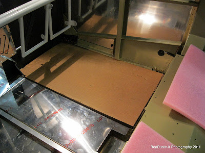
Here I have cut a couple pieces for a fit check...looks good, I like this setup. As you can see, I am keeping the Van's supplied center cover in this design scheme. My center console desing will attach to this later in some fashion...still TBD.
In this photo you can see my added 3/4" x 3/4" x 0.063" aluminum angle (4 of them). I plan to attach these extra pieces directly to the existing ones. The center two will be screwed into nut-plates in the center cover so they all can be removed for inspection and wiring. The other two will be pop-riveted in place.
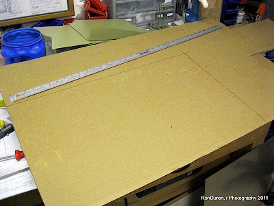
Now, to make the floor panel pattern. For this I used cardboard that I had kept from the Van's crates. I always keep stuff like this around for just such purposes, works great for layout. Much easier to get a fit with cardboard than alum sheet. Cheaper too if you screw up. Once I get it just right I will obviously transfer this to the sheet metal.

My first sub-floor panel in place...really liked the way this came out. Because we have a almost perfectly symmetrical plane...I was able to essentially use the same pattern for both sides just by flipping them over. That was nice.
After getting the first one just right, I transferred it to the second one and cut it out. Here they are side by side to give you an idea of my overall pattern. I used 0.040" sheet for this...might be a little overkill, but some guys actually go with 0.063" which I personally think is way too heavy.
With the sub-floors cut to size, I laid them in place, did some layout and then match drilled into the angle alum. I then removed the angle alum, opened up the holes and added #8 nut plates. I will use the same flathead screws that are used on the fuel tanks.

And voila, here is one screwed in place...looks pretty hot. I will add one more attach point and call it good. More on this later. Note, I may have to move my rudder pedals up 3/4" to accommodate this false floor. I'll decided this later.

Moving on to the canopy support for a change of pace. Just getting started with this. I am debating adding some structural strength to this sub-assembly. It provides roll over protection to the occupants and I've heard stories of it not being up to the task in some cases. If I can add some structure without adding a lot of weight and resources I will do it.

And lastly, here is my added angle alum support riveted into place. You can also see the flap assembly cleco-ed in place...still got a few details to do on that to finish it up.


Ron,
ReplyDeleteLooks great. I knew once you tried the pneumatic rivet puller you'd be hooked! ;) I will use mine a whole lot when I get to my fuse. The 10 fuse is large and full of pops. Keep up the good work.