Ron's RV7 Aircraft Factory


Welcome to my personal blog. This site was created as an informal description of my build progress in the construction of a Van's RV7 aircraft. A place where family/friends/builders/curiosity seekers can follow along. It is not intended to be a detailed description of every step in the building process as that would be much too time consuming. There are plenty of sites that do a great job in that arena, that is not my intention with this site. My intention is for this to be a philisophical/motivational/inspirational account of the emotional ups and downs of the life changing journey...and it will change your life. I hope this will give you an idea, through my eyes, of what its like to make this transformation. A note to other builders, I am not an expert so do not put your safety at risk by attempting anything you see on this site until you have done your own research, or send me an email so we can discuss it. Any deviations from the plans are not approved, nor endorsed by Van's Aircraft or myself. Thanks for visiting.


Sunday, December 20, 2009

Pete Vinton Engine Hanging! HOBBS 168.0 hrs

Yesterday I swung by Everitt airfield, home of Rocky Mountain Airpark, to visit Pete Vinton's RV8 project. This is a great airpark property being developed near Parker, CO. Pete is one of the partners. I like Pete quite a bit, in spite of the fact he is a Cornhusker fan! :) If I won the lottery tomorrow, the following day I would be buying a lot out there with a house/hangar/barn and a couple of horses. Check it out here,  Rocky Mountain Airpark

Pete recently took delivery of a partially completed RV8 fastback and mentioned  he might hang his engine. I wanted to see his project but the engine is what perked my interest since he had purchased the same one I plan to install in my plane. An Aerosport IO-375 (see previous post for a description). I was dying to take a look at this beast. This particular engine dyno-ed at a whopping 217hp at sea level and weighs the same as a 180hp -360!! Thats gonna be impressive in an RV8 fastback!

Although Pete was draggin his feet a little about tackling this job, mumbling about cleaning up the shop or something. His partner Wes and I tore into it like two kids on christmas! There is something that just isnt right about a pretty new engine sitting on a pallet next to an inviting airframe. Although Pete has owned several aircraft, including most recently a C180, he was not entirely familiar with Lycoming engines nor had he hung an engine on an RV before. Wes and I were even less experienced. How hard could it be I thought? It just four bolts...

Well, its only four bolts but it was a little tricky getting them all installed at the same time. Because we were all new to this, it probably took longer than it should have. But, a few hours later, Pete and I were having a cold beer admiring our accomplishment. Wes had a dinner date with his wife for their 22 yr marriage anniversary so he had to bug out before the deed was done so Pete and I finished it up without too much trouble.

As Pete noted, the engine is the "heart of the airplane" that pumps the lifeblood needed for powered flight. Without which, the airframe is just a collection of inanimate parts. To me, hanging the engine is symbolic of the birth of a child, it will be nurtured and grow from here, but this is its start. Certainly a big moment in the evolution of a project and I was happy to share in it. I also learned quite a bit so that when the day comes for me to do it myself, I think it will go much quicker with the knowledge I aquired on this day. It really was a great way to spend a saturday afternoon.


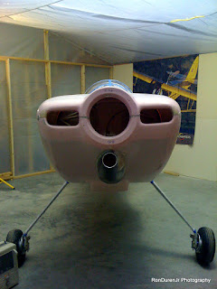
A couple shots of the project. Here you can see the unfinished engine cowl in pretty pink, thats how it arrives from Van's.


A nicely done 'fastback' with aluminum skirt.


Van's stock tailwheel, Pete has already purchased a 'Flyboys' tailwheel that has better ground clearance. He will swap these out later.


He purchased some aftermarket gear legs that are pretty nice. They are all one piece, machined in the shape of a fairing. He says these saved him 11 lbs over the Van's stock legs and look pretty slick.


The engine as it arrives from Aerosport Power in Canada, after uncrating...


The stock valve covers, Pete has ordered an upgrade to these that will say 'IO-375 Magnum' I belive?


On the engine hoist getting ready to move it into position. Wes's son Clay looks on in the background.


And a few shots of the finished results...pretty huh?


Wednesday, December 16, 2009

RV7 Cutaway Print by Tom Johnson HOBBS 168.0 hrs


Awhile back I mentioned an aviation artist that was doing cutaway poster prints of RV's. His name is Tom Johnson, and his work is quite good. He has done many custom prints of various airplanes from a Gee Bee Racer to Pitts for their owners. The idea came up for him to do an RV, so he started with the RV8, which I posted on my site awhile back. His second model is the wonderful RV7, and this is a view of the finished goods. I orered a numbered limited edition print, #5 of 100. It should arrive by Christmas...call it a Christmas gift to myself! :)

Tom Johnson RV ordering information

Wednesday, November 25, 2009

New Dynon Skyview HOBBS 160.0 hrs

As you may have noticed, the project has been slowing down for me. My strategy is to pay for the entire airframe with cash, which will serve as my down payment, to finance the completion of the project. So...there will be a small lull in activity while I save money for the wings.

I have been working on the tips here and there. They're looking nice, I think I am going to like the finished results. I'll post more on this later as I near completion.

So, when not building, the next best thing is dreaming/planning paint schemes, cockpit designs and avionics. Which, I gotta say, is quite fun! The avionics out there on the market for kit built planes is utterly amazing these days. I plan to have a 'glass' cockpit in my plane. For several reasons: #1, I have flown a G1000 and am amazed at the added safety these systems CAN add to your flying. You still need to practice good situational awarenesss and see and avoid techniques, but adding the features a glass panel provides is key for safe flying. #2, glass cockpits are definitely the future of aviation. And #3, I am a 'tech geek' and these glass panels are really cool!

I am considering several MFD (Multi Function Display) and PFD (Primary Flight Display) options. I think I have narrowed it down to two companies.

The first is Advanced Flight Systems. I really like their new Advanced DECK.

Advanced Flight Systems

Second is the new Dynon Skyview. This just came out this year at Sun-n-Fun. Dynon has been around in the kitplane market for quite some time and most of the guys have had nothing but good things to say about them. Namely, they seem to have great value for the money, homebuilders love that! :) I personally didnt like the look of their previous flight displays...frankly, they look kind of cheap. But this one changes that, the look of this new one is much more professional in its styling. It appears that Dynon is growing up and ready to play with the big boys in the market. That, along with their good track record in the homebuilt market, has me interested.


Both of these have the capability of using SV (Synthetic Vision), which is on my wish list. This is when you can see the 'virtual' landscape of the geography you are flying over right on your flight display, no matter the visibilty outside. Another great safety feature to have and also the way of the future. You can see it in action on the Dynon video.

Happy Turkey Day 2009!!! ...KPR (Keep Pounding Rivets!)

Sunday, November 15, 2009

Tips Continued.... HOBBS 154.0 hrs

And now the time consuming part starts. In the previous post I showed how I had fit and trimmed the tips and got them ready for install. One thing that I forgot to get a picture of is the aluminum strips I glued to the inside of the tips. The aluminum strips act to add strength for the pop rivets that are installed and dont pull through. Here you can see the first step. The holes have been match drilled. The tips have been countersunk and the aluminum has been dimpled in preperation for the pop rivets.


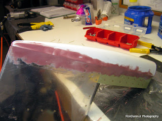
In my last post I mentioned the blue foam that I used to close the HS tip. Well, here you can see where that blue foam resides. Underneath the special fairing epoxy (the rust color, basically this is aircraft 'bondo') is the blue foam that has been glassed in place.


You can see the fairing work I am doing here on the elevators. Basically I am filling the seam, the pop rivet heads and low spots.


After it dries, I sand it to remove some of the excess fairing material and smooth the contours. I am getting it ready to glass the seam.


In this view, you can see how the two tips are starting to take shape. I will do several iterative processes to get these to match up nicely before I am done.


Its a little hard to see, but in this view I have added a 1" fiberglass strip over the seam. This is insurance to prevent the seam from cracking under the paint later. I use 'peel ply' over the fiberglass to keep it as smooth as possible.


This view shows the fiberglass tape after it has dried and the peel ply has been removed.


By adding the fiberglass strip, it adds a little height to the seam. So now I am using my fairing to not only fill the weave of the fiberglass but also to blend it into the sheet metal. I used a nice straight edge to get a real nice flat transition and to also fill any low spots I may have missed in the previous step. I am getting real close to being done with this. Now I will sand it smooth.


I wanted to show this shot because I really made the 'micro' very dry in this batch. By making it so dry, it was very thick in consistency...thick peanut butter-like. At first I thought it was too thick, but it really worked well for what I was trying to do. This was kind of a breakthrough in my education, in the future I will try to repeat this consistency.

Empennage Fiberglass Tips HOBBS 150.0 hrs

Now that the metal work is done, it is time to fit and blend the fiberglass tips onto the sheet metal. Vans recommends using blind rivets to attach the tips and call it good. Leaving the seams and rivets visible. You have to remember, Vans is very utilitarian in their aircraft design philosophy. Cheap, light and very basic is their building motto. Now, for me, that's quite boring. Half the fun of doing one of these planes is putting your personal touches on it, doing something to seperate it from the 'garden variety' RV7. Building it in a way that shows some craftmanship. So, with all that being said, I am doing this task a little different. I will fair the seams and fiberglass and rivet the tips in place. When I'm done, you will not see any seams, the tips will blend perfectly into the sheet metal so you wont know where one begins and the other ends. Not an original idea, plenty (most) builders do it this way. It looks very nice when done right. This is a time consuming task to do it this way, it also will add a little weight and expense.


So here is the HS with the elevators attached for fitting.


Here is the first fitting, I have just set the tips (white parts) in place so that I can get an idea where I need to trim the fiberglass for a good fit.


Here you can see the marks for trimming. I will use the dremel tool to trim away some of the fiberglass so that it fits nicely over the counterweight.


After trmming this is what it looks like.


And in this photo, if you look close you can see where it was trimmed. Underneath the tip is the lead counterweight.


Another shot of the tips in place, slowly trimming them down to a size I am happy with. If you look close,  you can see the blue foam that I used to close off the HS tip. I fiberglassed the foam in place to close off this gap.


You can start to see how the tips really make it look aerodynamic and clean. The tips give it a nice finished look. When I am finshed I will spray the tips with a filler/primer and they will look very nice if all goes well.

Drilling the Control Arms HOBBS 146.0 hrs

This is a task in the project where you need to 'match' drill the two control arms. Its a little tricky because the final size of the hole is 0.25" diameter and match it to the center bearing. So what I did was place a bushing with an outside diameter of 0.25" and inside diameter of 0.125". I placed the bushing inside the bearing and drilled a 0.125" pilot hole in both control arms. Then I disassembled the elevators and final drilled the holes to 0.25". This process gives me holes in both control arms that are aligned with each other and also with the bearing. Worked pretty slick.

Thursday, October 29, 2009

Andair Throttle Quadrant HOBBS 144.0 hrs

This is a throttle quadrant I came across, made by Andair, that I really like. I first became aware of Andair because of their nice fuel selector valves, which I plan to use. Turns out they do more than just fuel selector valves, they have some nice stuff on their website. Besides looking nice, I like the fact that this has flap control buttons on the throttle lever. Very handy for not only normal approach and landing but also for the surprise go around when not having to take your hand off the throttle is nice.


Last night, did some more work on the HS and elevator tips. Put on another coat of fairing micro to fill in some low spots on the HS and also glued in aluminum strips on the inside of the elevator tips for added rivet support...pics to follow.

Tuesday, October 27, 2009

Sheet Metal Work Done! HOBBS 138.0 hrs

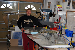
I had to add a shot of me with my completed left elevator. As you can see, I have already attached both elevators to the HS in this view. Cant tell ya how cool it is to see the individual parts assembled for the first time!!! Now for the fiberglass tips to finish up the empennage work.

Left Elevator Complete! HOBBS 138.0 hrs

Finally getting around to posting this, I finished the left elevator a few weeks ago and have already moved onto the empennage tips. Its safe to say all of the metal work is done for the empennage, from here on out it will just be 'glass work. The trim tab is not 100% done yet, but it just needs a little fine tuning and shaping, which I will do later. The left elevator is a little more involved because of the trim tab and the servo motor. Beyond that though, it is identical construction as the right elevator. So, rolling the leading edge needed to be done again. I felt a little more comfortable with this because I have now done it three times...with that being said, I'm still not going to miss this task, its kind of a pain. For aerodynamic reasons, the shape is not critical because this is never exposed to the airflow. But I do worry about induced stress at the rivet line in my leading edge and cracks forming because of this. We'll see as the airplane ages how well I did. It is something, that as the builder, I can be sure to keep an eye on as the plane ages. Another one of the cool things about being the builder, I will be completely intimate with every detail of the construction. That, in of itself, will make my flying safer.

My leading edge rolled and riveted, it'll fly!

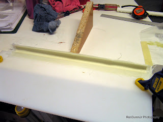
I needed to find something to create a 'mold' for a custom semi-circular fairing for the leading edge of the trim tab. So I found a piece of PVC that was about the right diameter for the job. Cut it in half and 'voila' I had a suitable mold. I used some clear box tape and hair spray for cheap mold release and the part popped right out when the resin had set up...nothing to it.


Here is a shot of the part after removing it from the mold. This is my first attempt at making a custom fiberglass part, came out alright. I wanted a way to close the gap on the bottom side of the trim tab to cut down on drag. I have not permanently attached this yet...still mulling this over whether to actually incorporate this into my design or not, but I probably will. Just trying to think about all scenarios that may cause me problems before installing it.

Here is another shot of the trim tab as I shape it. You can see I have sanded the trim tab skin in preperation for a coat of filler primer later.

And of course, the other side is also closed off...once again for aerodynamic purposes.

With this design I am able to really close up this gap nicely. I am not quite done yet, but its getting closer to being where I want it. I really like the look of this design deviation. I have to admit, moisture retention in the foam and added weight are concerns. I will address these topics again later.

Here is where my servo motor will reside for the electric trim. You can see I painted the inside of the skin in this area for added corrosion protection and for a more finished look if this area is ever accessed. It sure made me glad I wasnt doing all of the skin interiors.

I added some double stick tape to add a little height when the servo motor was mounted because there was an interference with the mounting screws. You can see it in the following pictures if you look closely.