Ron's RV7 Aircraft Factory


Welcome to my personal blog. This site was created as an informal description of my build progress in the construction of a Van's RV7 aircraft. A place where family/friends/builders/curiosity seekers can follow along. It is not intended to be a detailed description of every step in the building process as that would be much too time consuming. There are plenty of sites that do a great job in that arena, that is not my intention with this site. My intention is for this to be a philisophical/motivational/inspirational account of the emotional ups and downs of the life changing journey...and it will change your life. I hope this will give you an idea, through my eyes, of what its like to make this transformation. A note to other builders, I am not an expert so do not put your safety at risk by attempting anything you see on this site until you have done your own research, or send me an email so we can discuss it. Any deviations from the plans are not approved, nor endorsed by Van's Aircraft or myself. Thanks for visiting.


Thursday, November 29, 2012

Oil Door HOBBS 1617.0 hrs


Over the holiday weekend, I tackled the oil door fabrication. At this point of the project, I feel pretty comfortable with what I call simple fiberglass projects such as this one. My skills have steadily increased since my first exposure with fiberglass and it feels good to be at a point where I can tackle something like this without apprehension.

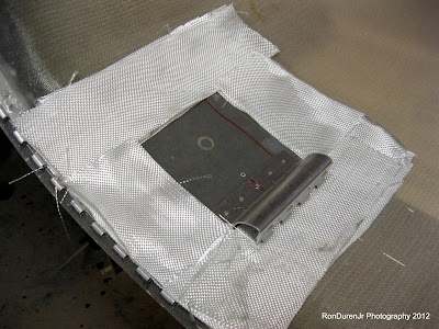
The Van's stock cowl may have a pre-fabbed oil door, but for the SJ cowl, you have to start completely from scratch. I had cut the access hole out very carefully to ensure I could use the cutout as my door. Now it was time to build the 'lip' that will close the gap in the reveal. First, I wanted to try and position the hinge strategically. I didn't have any instructions, so from here on out is all me...just winging it.


What it looks like from the inside as I get things situated...


As I get ready for apply the fiberglass (FG), I used clear box tape on all areas that I didn't want the FG resin to adhere to. This obviously included the door itself. Not only did I use the tape, but I also sprayed all areas that I didn't want anything to stick with my "redneck" mold release agent...AquaNet hair spray! Works just fine for this.

If you look close, you can see that I also added some modeling clay in the gap (reveal) between the door and the cowl. I didn't want resin getting in there that would be a pain to sand. You want to make sure you keep about a 1/16" min gap to allow for paint thickness on the door and cowl.


Once I got it prepped, I cut some 2" strips and laid them out to check the fit.


Next, remove the FG strips, mix up a batch of resin and start getting the strips saturated for placement. In this pic, you see the finished product...along with some peel ply strips on the rough transition areas. I didn't see the need to try and make this completely smooth since it will be on the inside...but I could see the argument to make this cosmetically more pleasing.


Again, notice the modeling clay in the gaps...and the tape wrapped around the door. This is obviously looking at it from the outside.


I let it dry overnight...come back out and carefully pop the door out. If you did a good job with your tape and mold release, it pops out pretty easy. You see that the lip is much bigger than I need it...I will trim this to size in a bit.


Here I am cleaning out the modeling clay...worked like a charm. Although I'm sure I'm not the first to do this little trick...I came up with this idea on my own...was very happy with the results.


Now its time to trim the lip. I didn't want this very big...I settled on about 1/4". Enough to give it a nice clean, closed up look, block out water and air, but also not too big to cut down on the access hole size.


A shot of me using my 1" rotary file mounted in the drill to clean up the rounded corners...


Not done yet, but its starting to take shape. I added some filler to smooth things out and clean it up a bit....and then did some sanding.


Reinstalling the oil door and hinge...the hinge is riveted in place with a coat of filler over the rivets. Once painted...there will be no sign of the hinge or the rivets...yielding a nice, clean look.


This gives you an idea what my 'reveal' looks like around the door...although not perfect (it looks hand crafted), it really came out pretty darn good and I was pleased. I can play with it more later before painting if I want to make things more precise, but for now, this is just fine.


A couple of awesome looking shots (or at least I think so!) of what the door looks like when I installed the torsion spring that came with the hinge. I want it to pop 'open' like this when it is unlatched. That way I can be sure, sitting in the cockpit during my pre-takeoff checklist that the oil door is, in fact, closed and not going to pop open on the climb out...in theory.


Here is a real quick video showing it in action...pretty cool eh?

Red Cube HOBBS 1617.0 hrs

Ok guys and gals, I'm back! I have bit the bullet and bought the added storage capacity. I think I will start my own website once the plane is finished to document my ongoing adventures flying Wablosa. At that point in time, I will just leave this build site up as an inactive archive of the build process. But until then, I needed to purchase this storage to keep it active and keep on trucking!
 
Turkey day was wonderful, hopefully you all had a good time with family/friends and ate some good grub! I put in a strong week in the factory over the holiday weekend...not great, but strong...pushing me to 1617.0 hrs on the HOBBS. I am hoping with my month long holiday break from school in Dec/Jan to be knocking on the door of the 1700 hr threshold by the first week of the new year.
 

If you remember back to my post when I received my engine and its contents, I didn't know what this wiring harness was for? Well, turns out it attaches to my Plane Power 60A alternator...mystery solved with a little help from the Internet and my trusty iPhone I was able to confirm this....technology is great. I will hook this up soon now that I know what it is.


Adding a wire from the ANL current limiter up to the battery.


Starting to lay out my Aveo switches for wiring. This is the lineup I am looking for to occupy the ten switch locations on my Aerosport carbon fiber panel. I will probably add a couple more (boost pump, pitot heat) but they will be mounted in my center console. Again, notice, I am following the Vertical Power pinout chart....so handy!


Here I have started to add wires to the connector for the switches. This connector (cant remember if its J1 or J2?) will plug directly into the Vertical Power box.


Cant have power without ground...in this pic, you can see I am doing my ground wires for the switches. These will all go to my "forest of tabs" ground block on the firewall. Even though it is just a common ground, I am still labeling it. If I have to troubleshoot any wiring later...I want my ground wires labeled as well. Some will argue its not important, a ground is a ground...I disagree, there could be good reasons for knowing exactly "which" ground you are dealing with...i.e., intermittent connections, ground loops, etc.


After agonizing for what seemed like forever...actually I think it was months...I finally made a decision for my fuel flow transducer, aka the "red cube". I was considering a few options. #1, mount it after the boost pump in the cockpit. #2, mount it downstream from the fuel injection servo and before the distribution spider...or #3, after the mechanical fuel pump on the firewall. They all had pluses and minuses. This location is what I settled on, it is option #3. I think it is a good compromise.

Here is my info dump of each option listed above from my research on this pesky little red cube. I advise you start thinking about this ahead of time and come up with a plan.
  1. Pros: Inside the cockpit, less potential for fire. It is recommended to firesleeve the cube if it is mounted FWF. It is an aluminum cube, alum doesn't play well with hot FWF fires. Cons: reports are that your fuel flow readings will spike while the boost pump is on. The mfg recommendations say to put it downstream from both the boost pump and the engine driven fuel pump. This was my first choice...most feedback from other builders is that the spike is hardly noticeable. Even though ultimately I didn't go this route, I wouldn't have a problem with this mounting strategy...I think a lot of the RV10 guys put it here.
  2. Pros: This is technically where they recommend you put it...after both pumps and the servo. Many builders go this route with good results. Cons: With a crossover exhaust, the space is limited and the location puts the cube in close proximity to my hot exhaust, which they don't recommend...and I didn't feel good about either. Hot fuel and vapor lock is constantly in the back of my mind as I plan fuel flow routing FWF. This was a location I preferred and consumed a lot of brain cells thinking about. I looked and looked and played around with many different mounting schemes to try and come up with something I felt comfortable with...and I never got there.
  3. Pros: Downstream of both fuel pumps, mounted on the firewall so there will be no engine vibration imparted on the cube, and easy access for maintenance/mounting. Cons: Its mounted FWF, which isn't ideal in my mind, I still don't like the idea of putting this puppy in the engine compartment but its a risk I am willing to accept in the event of a fire. At this time, I don't plan to wrap it in firesleeve.
 
Lastly, now that you've seen my mounting location...let me add, DON'T mount it with this ORIENTATION!! After I made my nice little bracket and got it mounted, and really felt good about my decision, I noticed I mounted it BACKWARDS! The flow direction is wrong in this pic...I need to make a new bracket and flip it around 180 degs. D'oh!! Mistakes will happen...just glad I caught it now, rather than later.

Wednesday, November 21, 2012

The Home Stretch HOBBS 1603.0 hrs

Hey, its me again...its been a couple weeks since I last posted. Not for lack of activity, I assure you, if you were to happen by the factory you would hear the sounds of progress being made. I finally crossed the 1600 hr threshold, and gosh did that seem to take forever. Admittedly, my average hrs/week has been down lately...around 10 hrs, so that contributed to the slower pace.

I now have 21 weeks left until my birthday in April, my self imposed finish line so I'm in the home stretch of this long journey. If I average 10 hrs a week, that will put me over 1800 hrs...if I can get back to my 15 hr/week average it'll put me over 1900 hrs. I estimate it will take 1800-2000 hrs when all is said and done. As you can see, I am definitely in the ballpark.

I told my new hangar landlord, Bob Markert, that my move in date will be the middle of January...I've put a stake in the ground and am committed to this. After plenty of thought, I wanted to wait until after the holidays to mess with the move and transition...hopefully it won't be too disruptive to my progress.

You're probably wondering why I don't have any pics to post? I do, but blogger has informed me that I have reached my limit for free picture storage...1 GB. That was a nice surprise, not...they dont tell you this when you start! Now I am kind of stuck. And for others out there following my path, if you keep your pics at a smaller resolution, you can avoid this fate. Read the fine print...or try word press.

I cant post any more pics until I buy extra storage to the tune of $30/yr. Not happy about it, but gosh, what did I expect...storage isn't free, I should know...I'm in the business. I'll probably just buy the added storage, but I am looking at my options first...or lack of. Until then, stay tuned...progress pics are coming! Have a wonderful turkey day with your friends/family...and try to sneak away for some time with the mistress over the long holiday weekend!

Wednesday, November 7, 2012

Battery Cables and More Wiring HOBBS 1588.5 hrs

I was up at o'dark-thirty Saturday morning working on the Vertical Power harnesses. I did this on the dining room table for more comfort, soft music, fireplace going, nice...the lighting isn't so good though, which is why you see my little LED flood light. The iPad has my Vertical Power pinout...very handy as I work my way through these.
 

If you are going this route on your plane...some advice, be sure to use the correct length wire for each application. There are 20 ft, 10 ft and 5 ft lengths in the harness bundle. So, you will have to do some planning to use them correctly. Also, if you read this soon enough...don't run wires to your nav lights/strobes or any thing that will terminate at the VP box. It will be wasted effort. In fact, I need to either rent a crimper from VP or send my shielded nav/strobe wires in for crimping since they terminate at the box. Part of the learning...


Labeling all wires as I stuff them into the connector.


These are about 95% done...as mentioned, they are missing shielded wires for the strobes.


I started running my heavy duty 4 AWG wires...this one from the starter contactor to the starter.


That was all well and good, until I read in the VP instructions (which are great by the way) to NOT hook up the starter. If I mistakenly do something to engage that starter, my very pretty prop will be running into some interesting stuff. I pulled it off...and taped over the end just to be safe. Part of the large learning curve for a Mechanical Engineer as he ventures into the world of flowing electrons!! duh! Think...


Routing from the master contactor to the battery. The black ADEL clamp in this pic is temporary as I need to order some more of the white high temp SS versions for the FWF. Notice the red shrink tube designating positive (+)...maybe not needed but a nice touch I thought.


I cut this boot back...its designed for a right angle application, not straight on...I didn't like the way it bunched up...looks better this way I think.


Added a conduit on the inside of the firewall for wire routing. The RG400 coax going to the 978 MHz UAT antenna (from Delta Pop) is the first occupant. This will terminate at the GDL39.

 
This pic shows my 978 MHz UAT antenna location...I will put the transponder antenna behind the baggage bulkhead so I have 60" separation between the two.


I realized I never showed a pic of the back of my seats. They are very professional looking, just like the rest of the seat. A hard plastic reinforcement is attached where the seat rests on the fuselage cross support. The center device is for adjusting your lumbar support. And of course, each seat has a map pocket.

Crimping Coaxial Cable HOBBS 1588.5 hrs

Crimping (terminating) RG400 coaxial cable is pretty straightforward...with a little guidance. I learned this in my SportAir electrical class, but I had to refresh my memory since its been awhile. Here is a short guide for your reference if you've never done it before.
 
 
First, go to Vertical Power's website, Marc has some very helpful documents that you should read. For this task, click on the "Connector Service Manual" link.

 
I found some inconsistency in these strip dimensions in my google search. Above is what I used and it worked fine. Bob Knuckles, for example, uses different numbers. It leads me to believe this isn't that critical as long as the shield extends far enough for a good ground contact with the crimp. 
 

They sell special stripping tools for this task...I, amazingly since I like tools, did not buy one. I just used a razor blade...worked fine for the small number of times I need to do this.


Slide your center pin on...notice a small gap between the white insulator and the pin, this way you know it is fully seated.


Use the proper Coax crimping tool for the job...no pliers!


First crimp the center pin...these pliers do both the pin and the main connector housing.


Before sliding the connector housing on, slide the sleeve and a piece of shrink tube on first. Notice that the silver braided ground sleeve slides over the connector.


Again, use your ratcheting crimp pliers to secure the connector.


Slide your shrink tube over and apply heat...there ya go, nothing to it. You can use color coded or label printed shrink tube also...on this example I didn't do either, but the opposite end will have some identification.